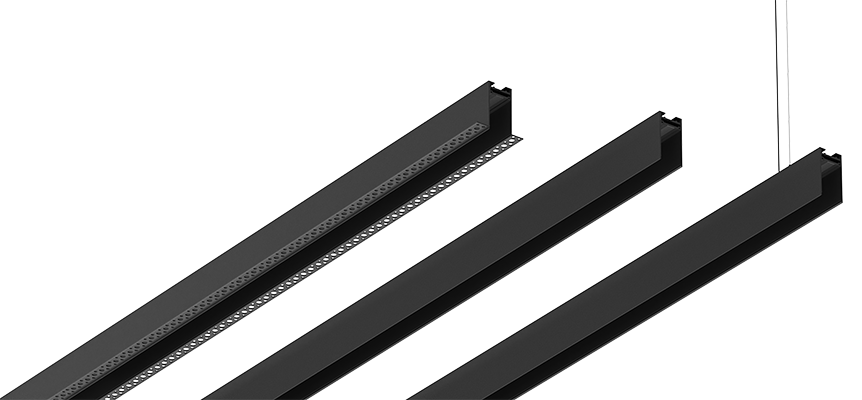
Magfinity Installation Process
There are three types of installations for the Magfinity series:
1) Surface Mounted
2) Suspended
3) Recessed
Below are the different options easily described, step by step, for a smooth and correct installation.
Surface Mounted / Suspended
Surface Mounted / Suspended options
Surface Mounted
Surface Mounted Installation Manual
Step 1: Measure MAGfinity track Layout
Taking the MAGfinity track and terminal box dimensions into consideration, measure and draw your desirable track line on the drywall surface.

Step 2: Insert Pin
-
Insert the pin into the slots on the power plate and terminal box.
Step 3: Attach Terminal Box
Using the coupler, attach and fasten the terminal box to the MAGtrack.
Step 4: Power & wiring
Find the ideal placement for remote LED drivers either at the nearest utility room or the track power box. From there, run the wires to approximate terminal box location.
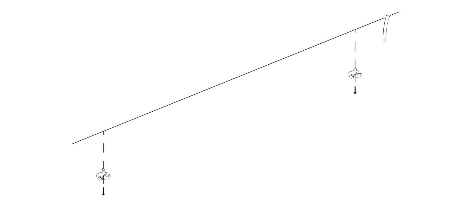
Step 5: Attach the mounting clips
Take a precise measurement at the MAGfinity track for straight and leveled clips positioning. Attach mounting clips to your surface with a screw.
Step 6: Mounting the MAGfinity track
Connect power wires to the terminal box. Take internal power plates out of the MAGfinity track and place it into the opening. Make sure your track is straight and level. Screw the fixture through right into a bracket, one by one.
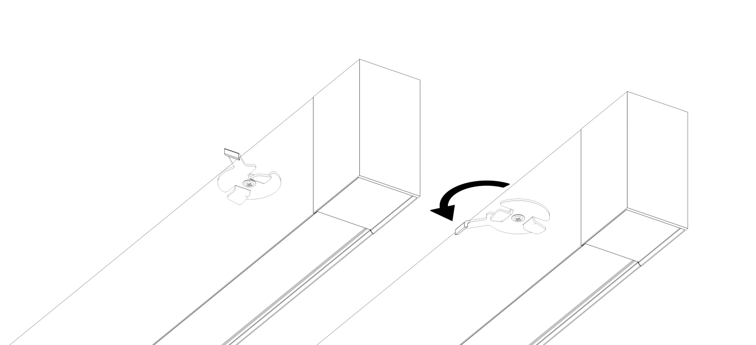
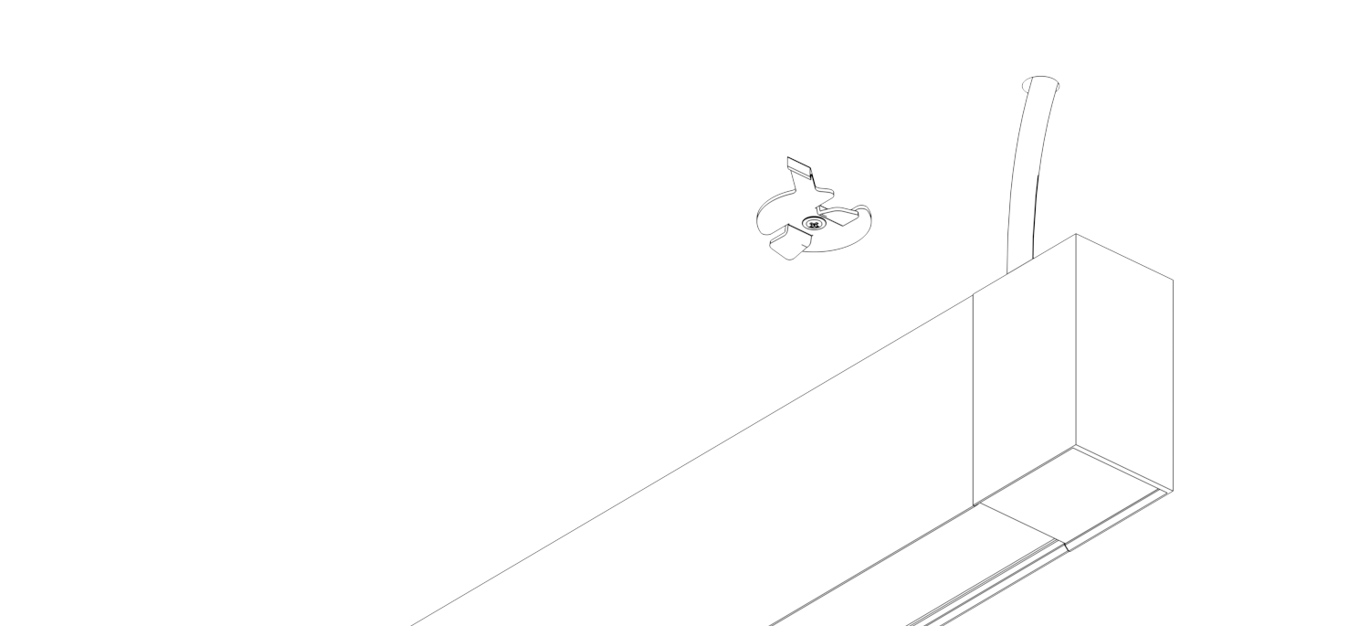
Step 7: Secure MAGfinity track
Place the MAGfinity track securely against the mounting clips, make sure the clips sit in the track. Firmly rotate to fasten each clip.

Step 8: Joining MAGfinity track: Pin & Coupler
If needed, connect all the MAGfinity track's consecutive elements with a pin in between the power plates located on each component.
After successful pin connection, secure two MAGfinity elements by coupler
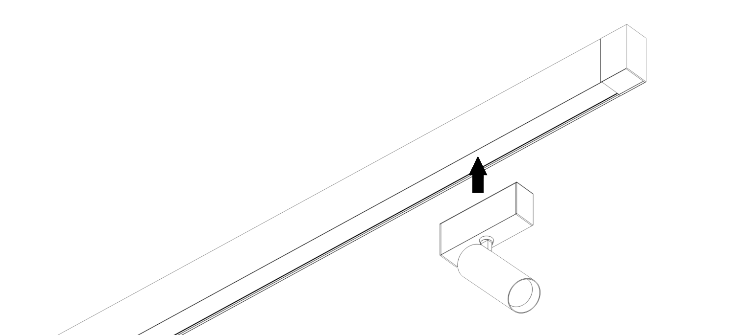
Step 9: Placing the luminaires
Snap-in place the desirable luminaires. Enjoy the installation!
Suspended
Suspended Installation Manual
Step 1: Power and Wiring
Find the ideal placement for remote LED drivers. Either at the nearest utility room or the track power box. From there, run the 16-18 gauge wires to your J-Box location.

Step 2: Take Measurements
-
Measure the desired height from the fixture to the ceiling. The power feed cable is 16 ft long, the fixture can be placed within that distance.
-
Make sure to save 6 inches for electrical connection at the j-box. And save 6 inches for electrical connection at the terminal box.
-
Cut and discard excessive cable length.
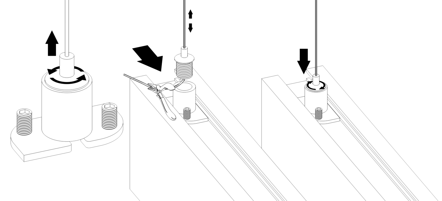
Step 3: Aircraft Cable
-
Unscrew the grippers from the hangar mounts.
-
Slide the hangar mounts onto the top side of the track.
-
The aircraft cable’s length can be adjusted through the gripper.
-
Cut and discard excessive cable length.
-
Complete step by screwing the gripper back to the hangar mounts
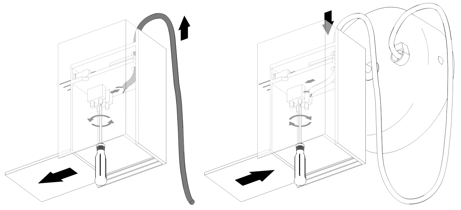
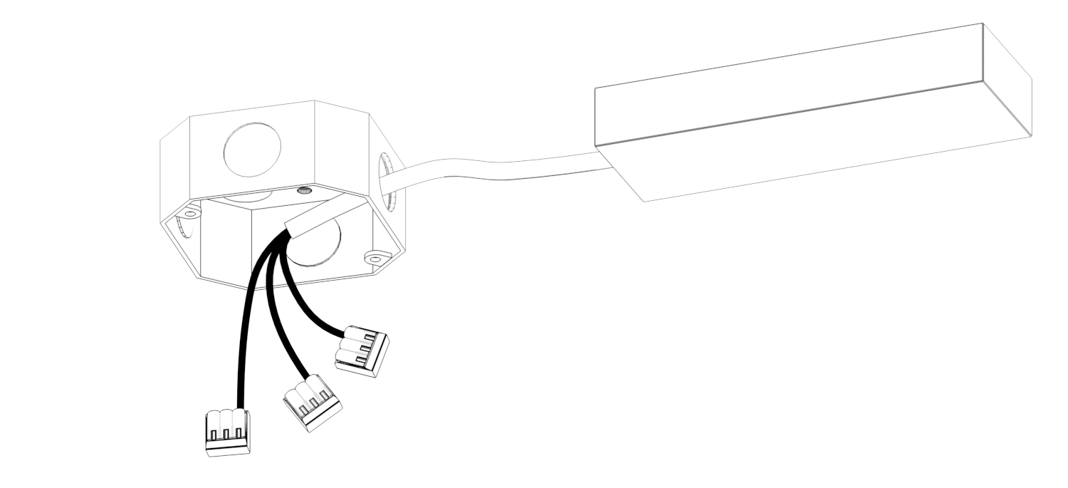
Step 4: Terminal Box Wiring
Take the terminal box out and remove the cover by sliding out. Using a screwdriver, remove the pre-installed wires from the terminal box. Make sure to keep the internal wires untouched.
Insert power feed cable from the canopy set to the terminal box and fasten them with a screwdriver.
- Black is negative (Black to Black)
- White is positive (White to Red)
Step 5: Attach Terminal Box
-
Insert the pin into the slots on the power plate and terminal box.
-
Using the coupler, attach and fasten the terminal box to the MAGfinity track.
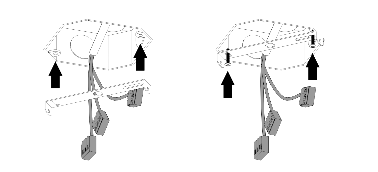
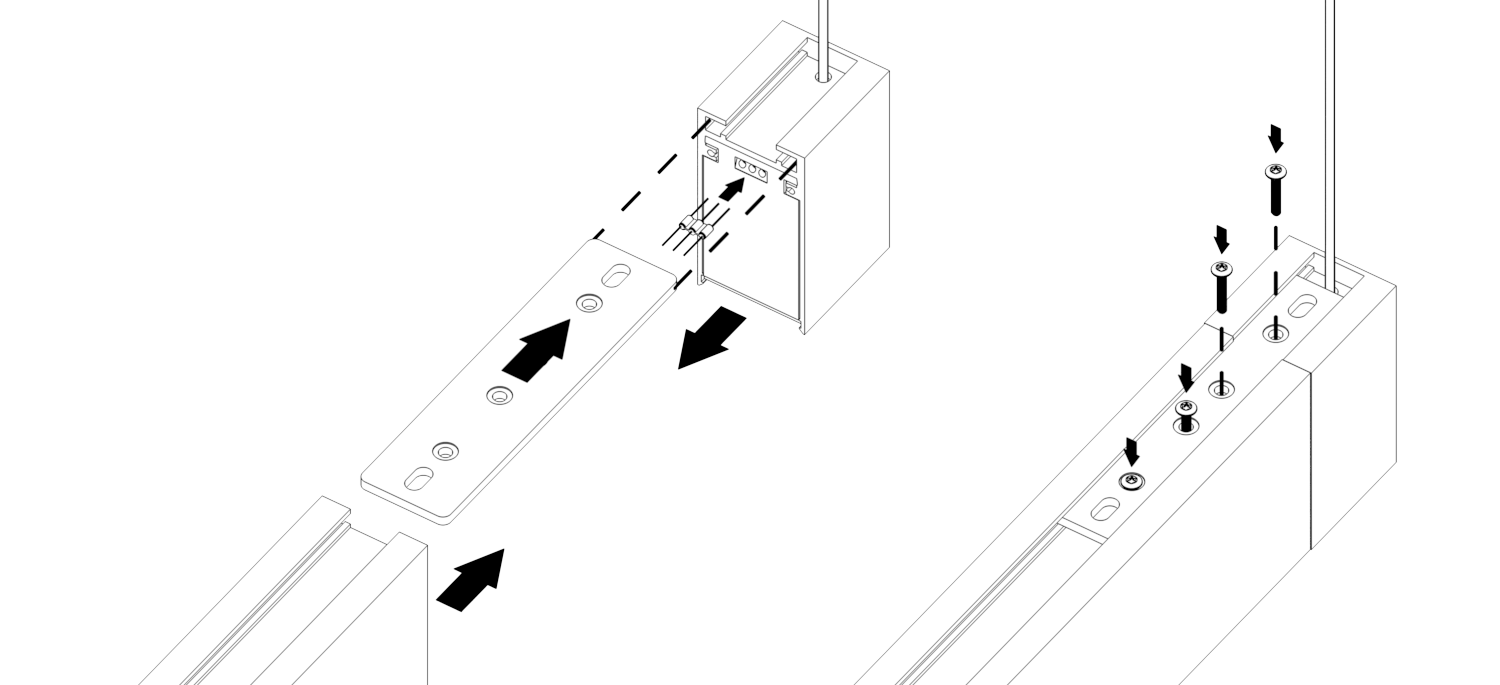
Step 6: Mount Bracket
Fasten the mounting bracket to the J-box with the provided screws.
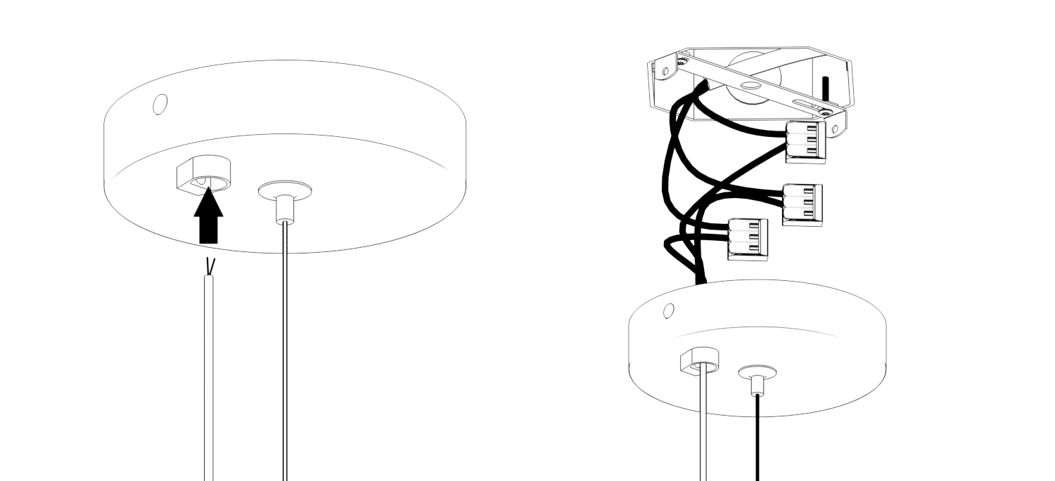
Step 7: J-Box Wiring
-
Pull the feeding cable through the cable bushing on the canopy plate.
-
Connect the feeding cable wires from the inside of the canopy to the preinstalled electrical wires inside the J-box using WAGO connectors.
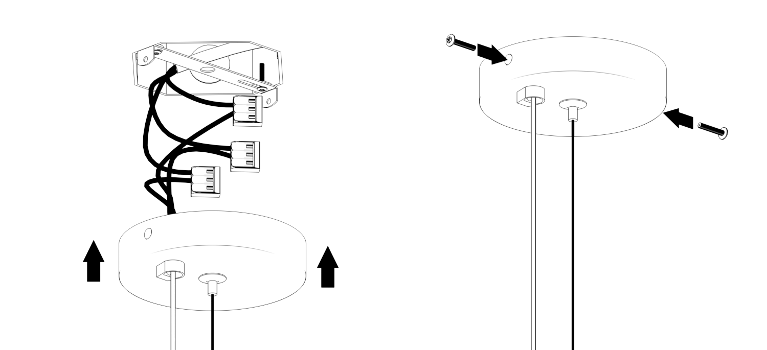
Step 8: Canopy Placement
Using the screws on the side, Insert the canopy cover plate over the mounting bracket. Securely place it on the j-box.
Step 9: Joining MAGfinity Track
If needed, connect all the magtrack's consecutive elements with a pin in between the power plates located on each component. Please make sure to slide the hangar mounts onto the top side of another MAGfinity track before connection.
Step 10: Placing the luminaires
Snap-in place desirable luminaires and enjoy the installation!
Recessed
Recessed Installation Manual
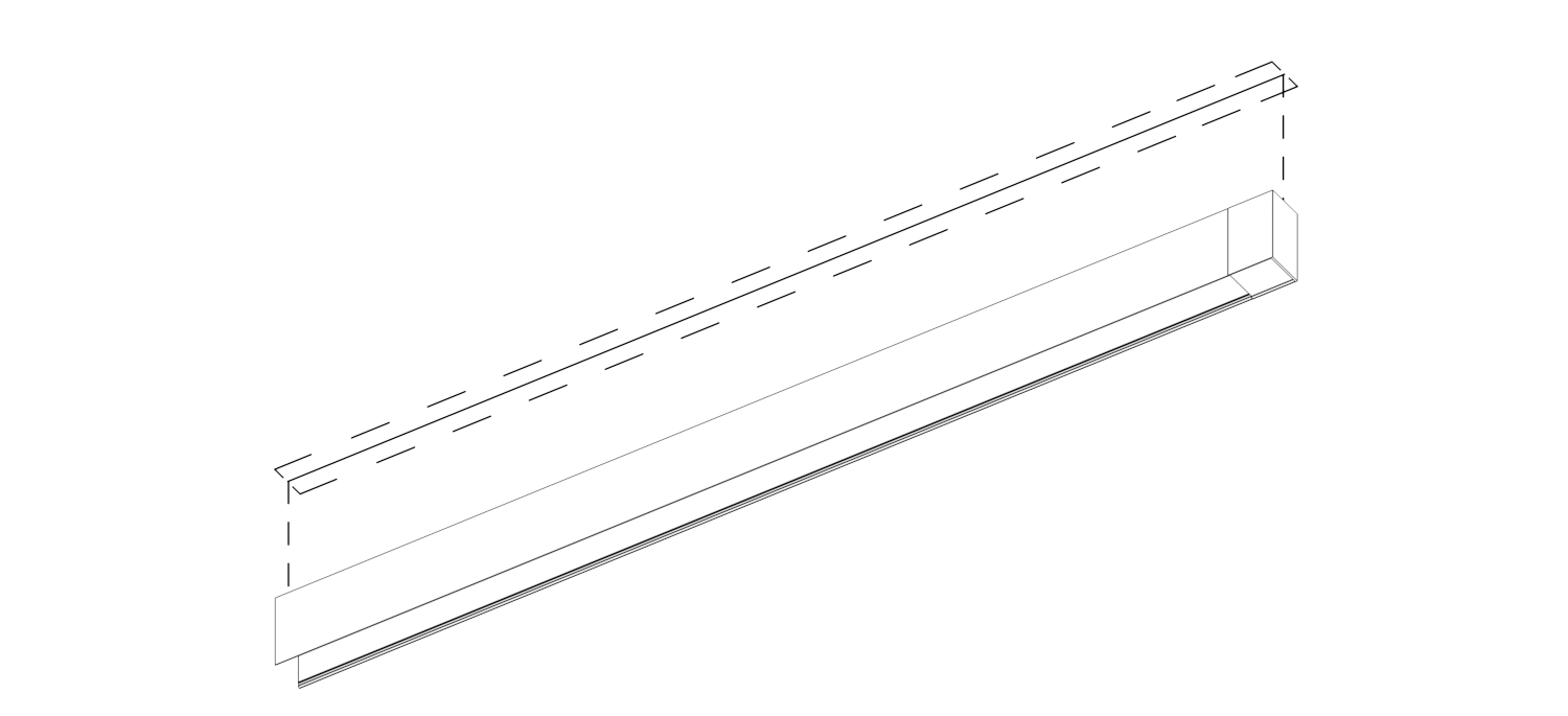
Step 1: Measure MAGfinity track Layout
Taking the MAGfinity track dimensions into consideration, measure and draw your desirable track line on the drywall surface.
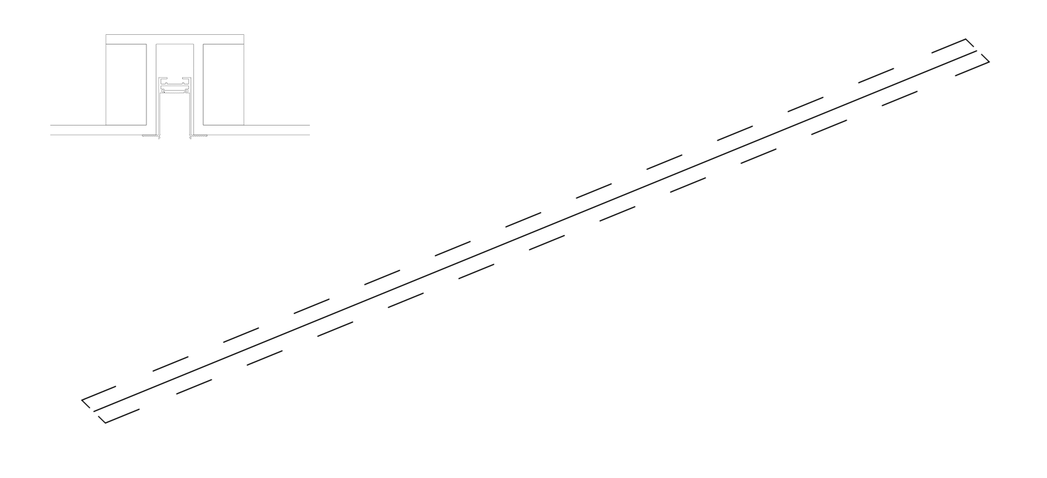
Step 2: Cut Into Drywall
Cut into drywall to create opening. Make sure the cut is precise and does not exceed 1/8" of a fixture size for a sharp looking installation.
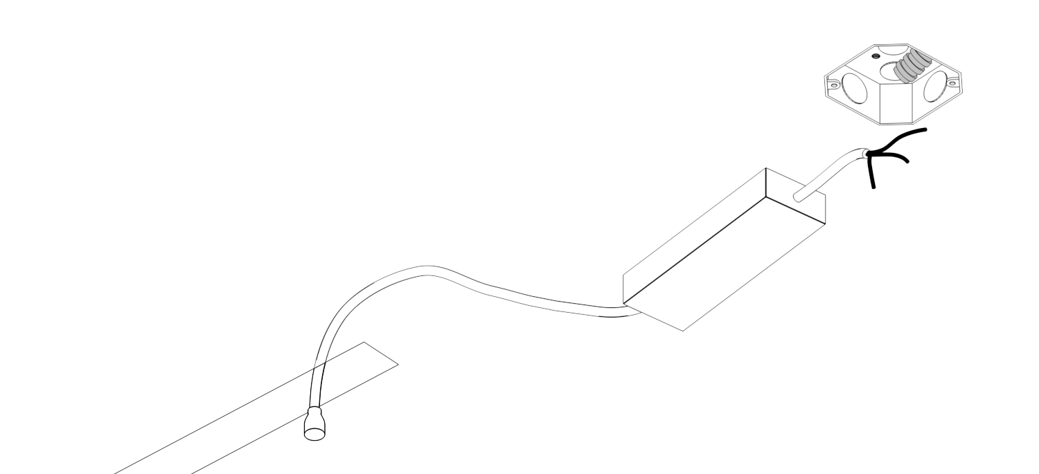
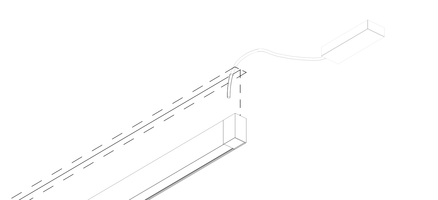
Step 3: Power & Wiring
Find the ideal placement for remote LED drivers either at the nearest utility room or the track power box. From there, run the wires to either end of your opening.
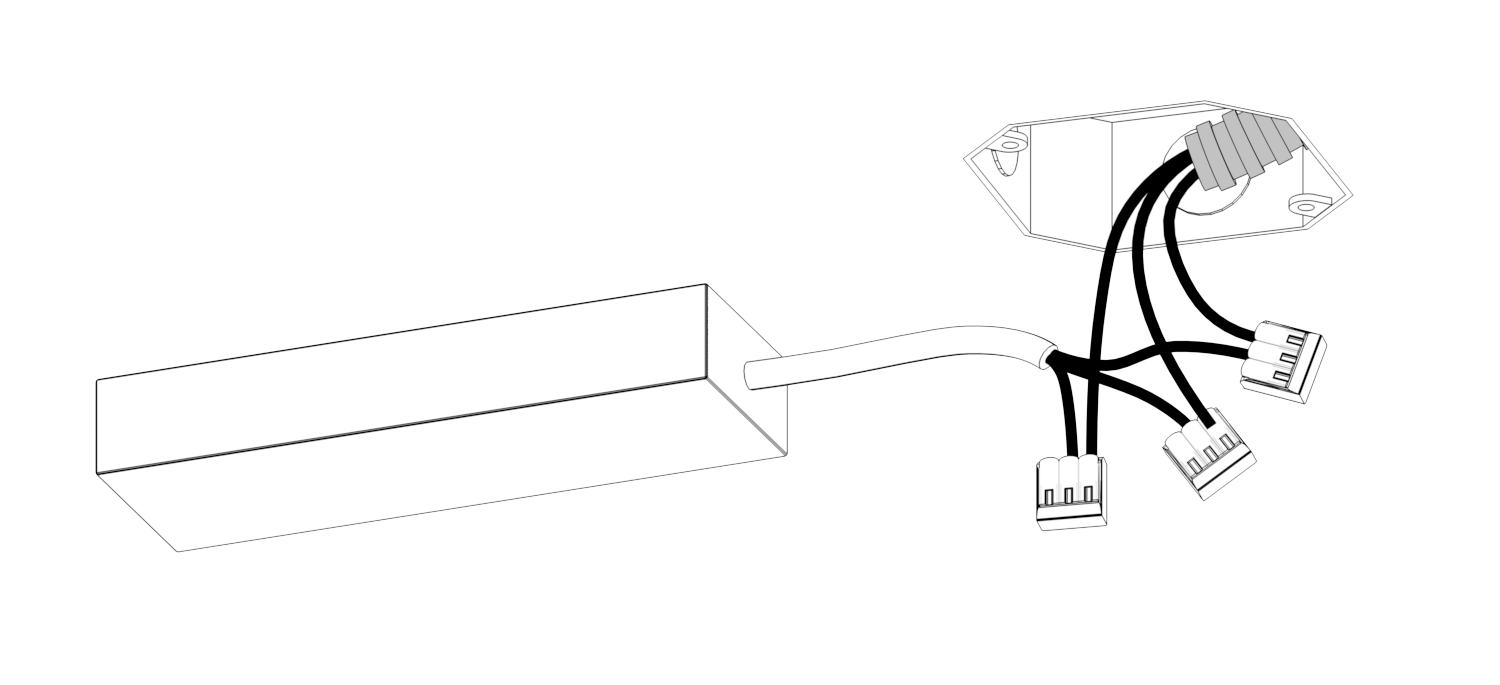
Step 4: Attach Connector
Using WAGO connectors, attach 3 pin connectors to your power supply wires. Each power supply requires 110/277 VAC connection.
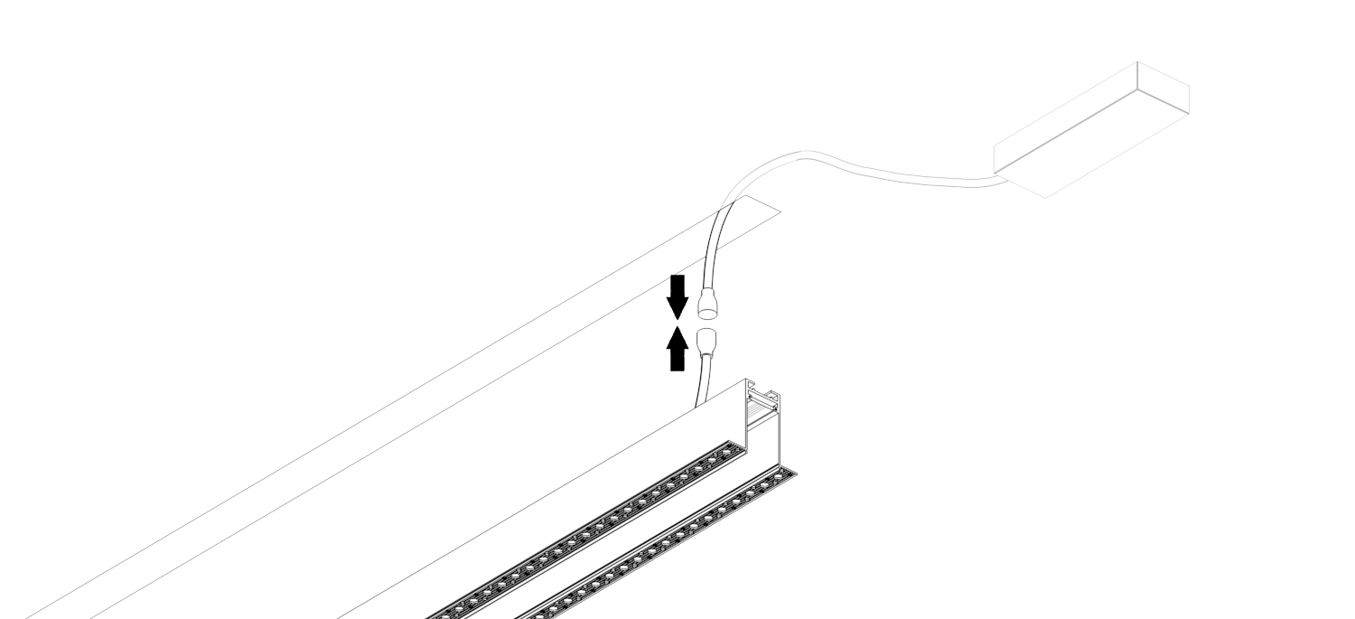
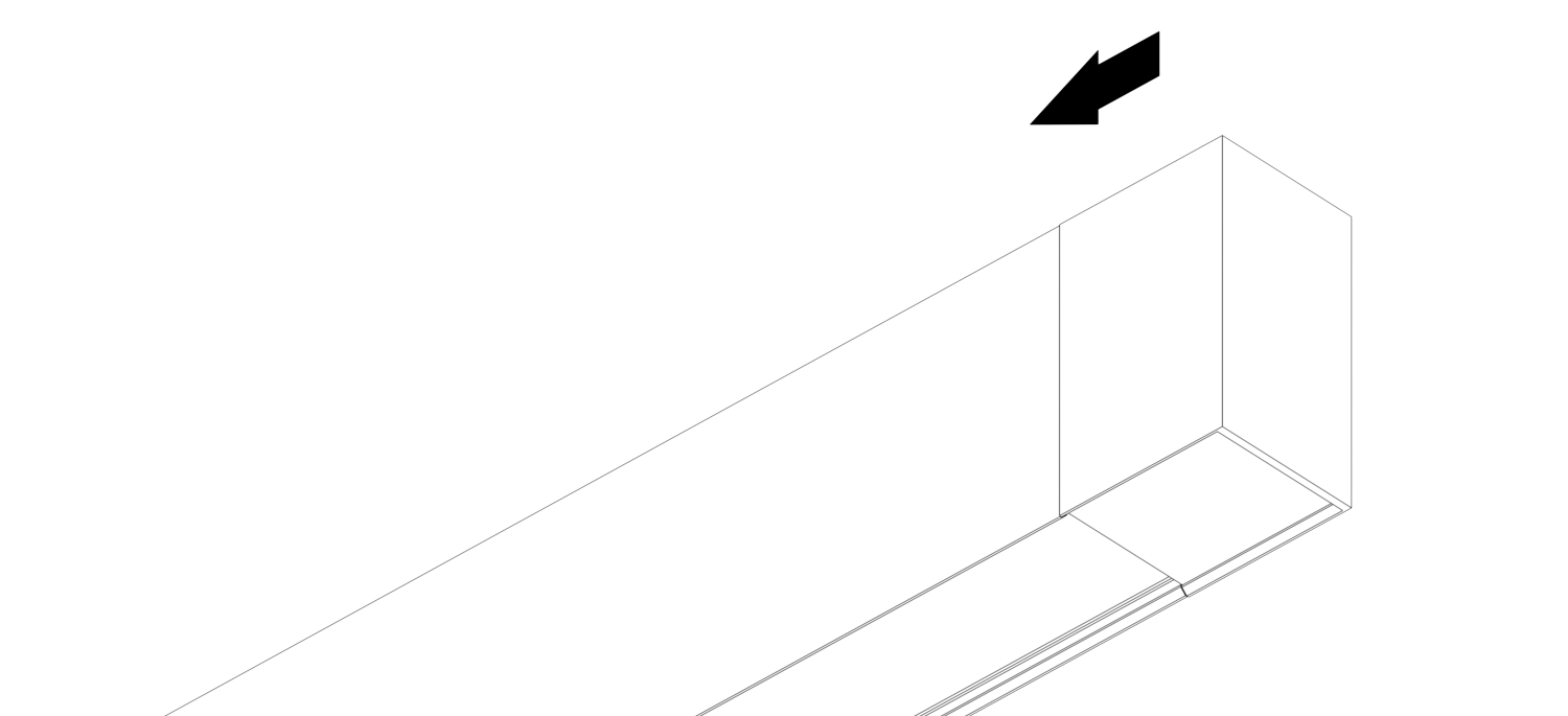
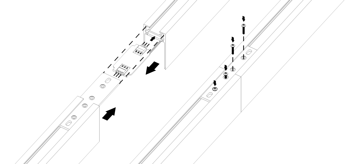
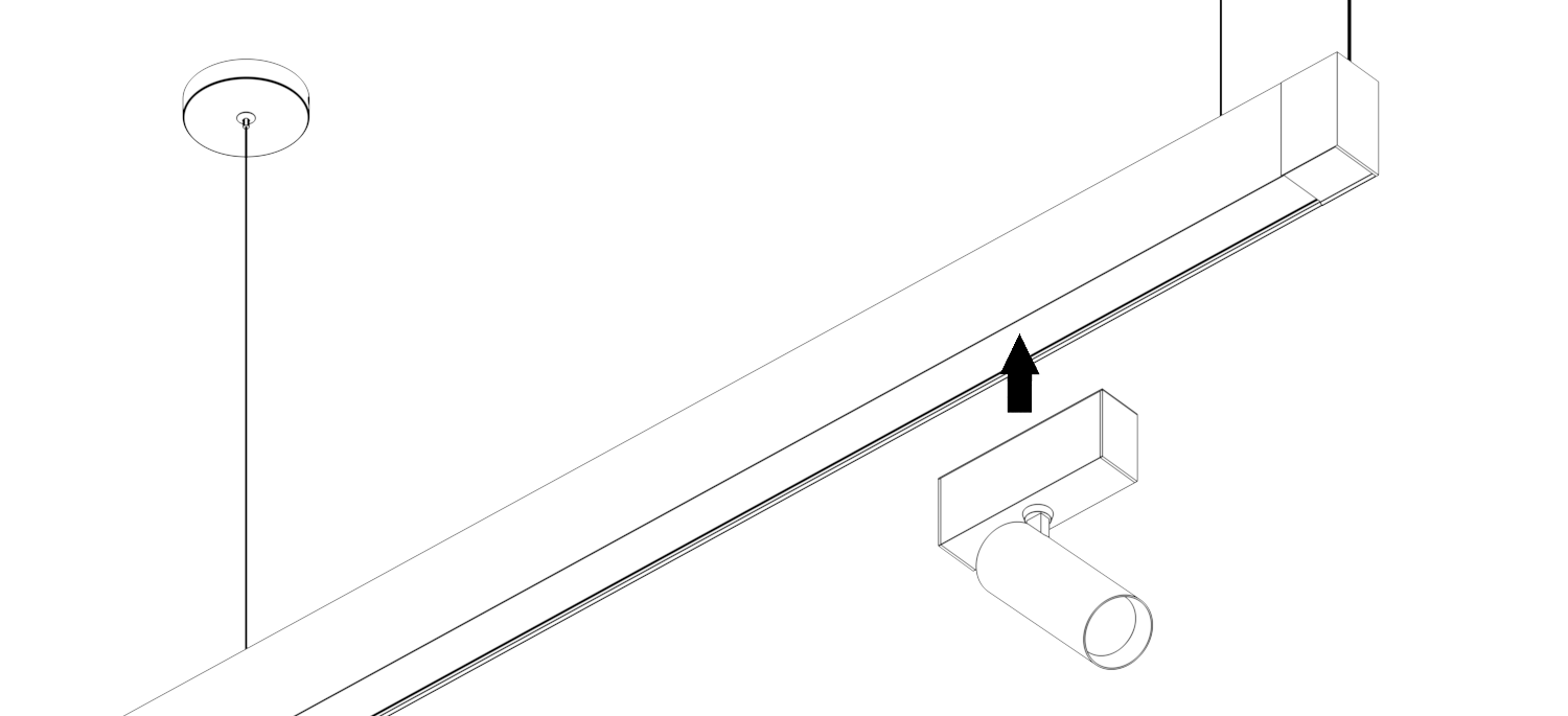
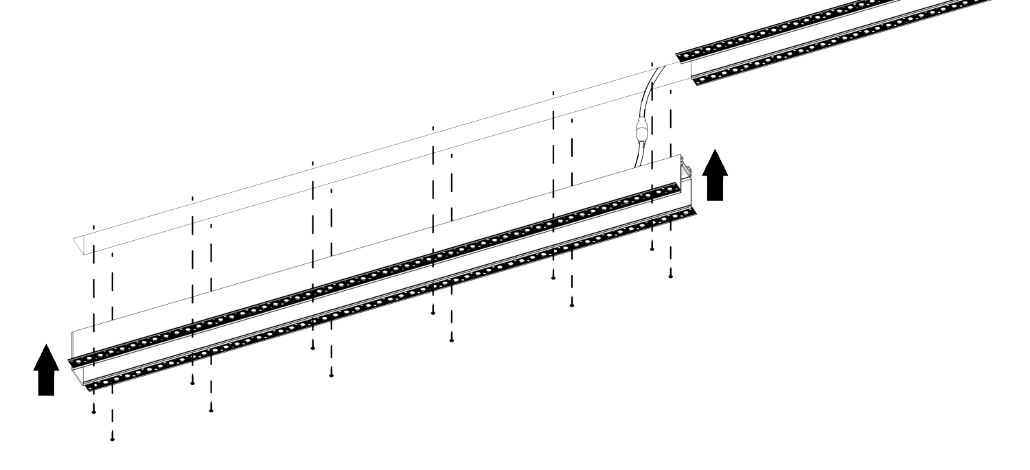
Step 5: Track Placement
Join the flexible 2 pin connectors first and place the track into the drywall opening.
Note: For single fixture run, attach the end cap to both ends.
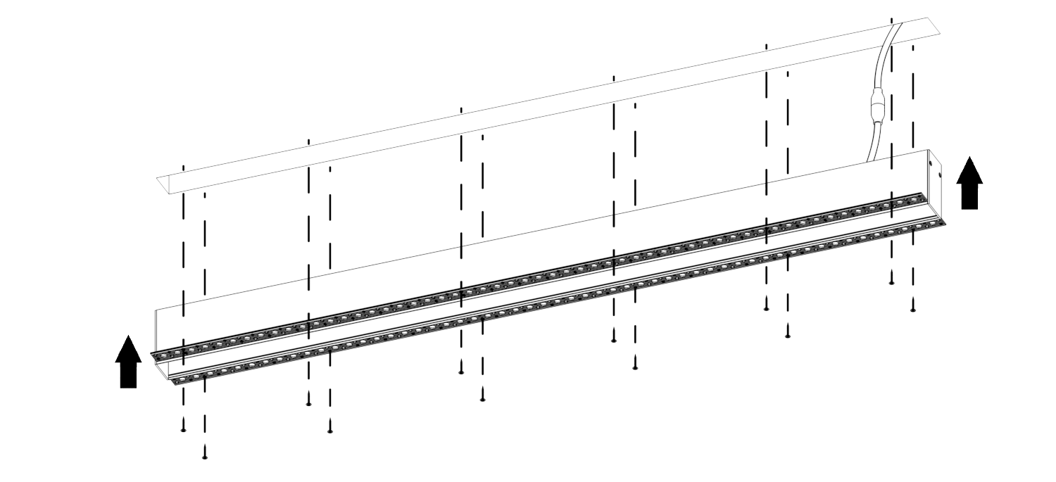
Step 6: Secure Track In Place
Secure the track with the screws through the trim holes around. Make sure the track is secured.
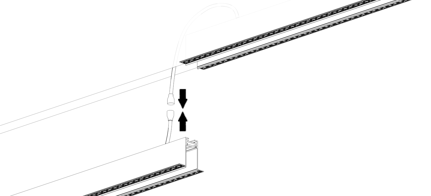
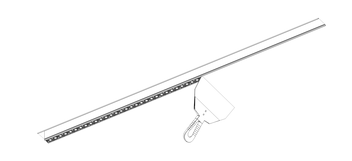
Step 7: Connect Next Element
If needed, connect all consecutive elements of the track with 3 pin connectors located on each component. Secure into place by following step 6 with the newly consecutive tracks.
For multiple fixture runs, attach the end caps to the beginning and the end of your run.
Step 8: Secure Connected Track Into Place
Secure the newly connected track with screws through the trip holes around. Make sure the track is secured.
Continue Step 7 and 8 for any continuing tracks.
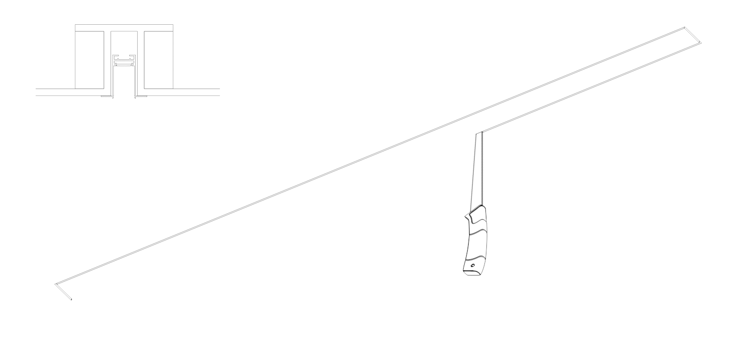
Step 9: Patch Plaster
Using painter's tape, cover the track slot. Add plaster on the track trim and smoothly patch it with a compound knife. Even the patched drywall surface out. Let it dry 12 hours minimum.

Step 10: Finishing
Sand, the patched area, make sure to sand along the taped edge area for a smooth transition.
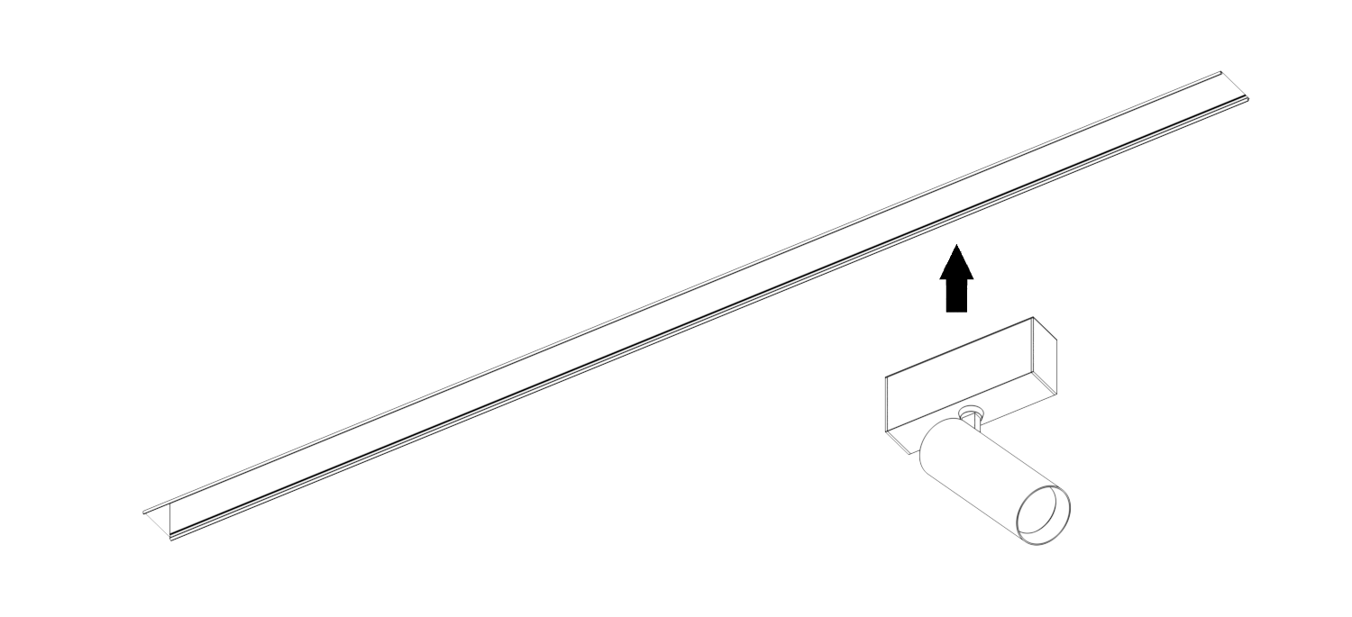
Step 11: Luminaire Placement
Snap-in place desirable luminaires and enjoy the installation.
© 2024 MAGfinity®. All rights reserved
We use cookies, both our own and third-party cookies, to provide you with more options when using the site. By continuing to navigate the site, you automatically agree to their use.
Accept